 a journal of interesting technical ideas . . . a journal of interesting technical ideas . . .
GNS3 is great for simulating networks, but what happens when your lab needs to include devices outside GNS3 (like physical hardware)? Wouldn’t it be nice to include hyperlinks to “real” assets in the GNS3 diagram? There’s a way to do this!
Let’s think about the things that might be interesting to add to a GNS3 topology . . . the home firewall, switch, server. You could even imagine adding IoT devices to the diagram and controlling them from a GNS3 appliance.
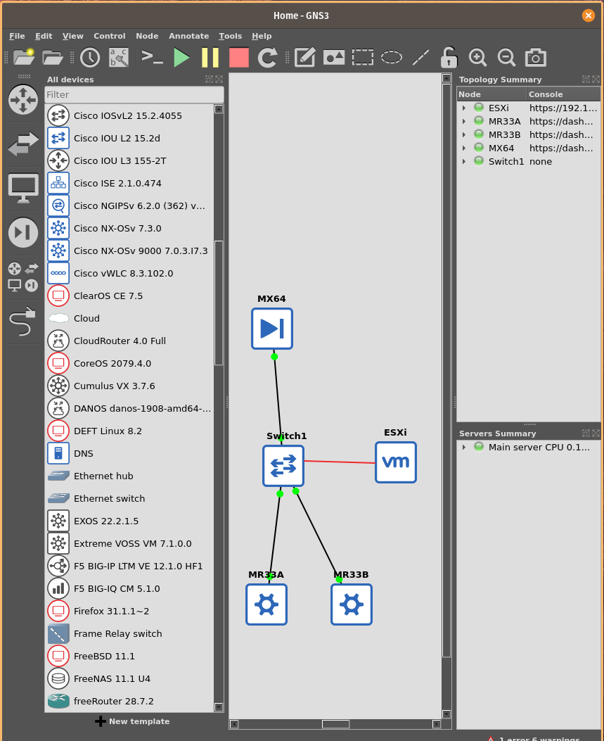
For this demonstration, I’ve built a simplified view of my home network. I have a Meraki stack - an MX64 Security Appliance (“Firewall”), an MS220 switch, and some MR33 access points. To make this a little more interesting, I’ve including my ESXi server.
To add a device, drag a “cloud” appliance into the topology. Right click the cloud and change the symbol. For instance, you can see that I changed the top cloud to use the firewall symbol. I also changed the label to “MX64”.
There’s not an Affinity Blue symbol for access points, so I chose the “cog”. You could also grab a picture or manufacturer icon. Just for fun, in the third picture I went to Google Images and copied a picture of a Meraki access point. I don’t think it looks as good as the cog, but it demonstrates how you could use this technique to introduce all kinds of graphics.
To extend this concept, in that same example I created a stand alone book icon that links to my documentation. It would be easy to imagine a link to a Google doc or Sharepoint site in the same way.
If you use outside graphics, keep in mind that GNS3 recommends a maximum height and width of 70px. I find that the “summary view” size on Google images works pretty well. You can also resize existing graphics with Imagemagick:
convert -background none download/meraki.svg -resize x70 meraki.svg
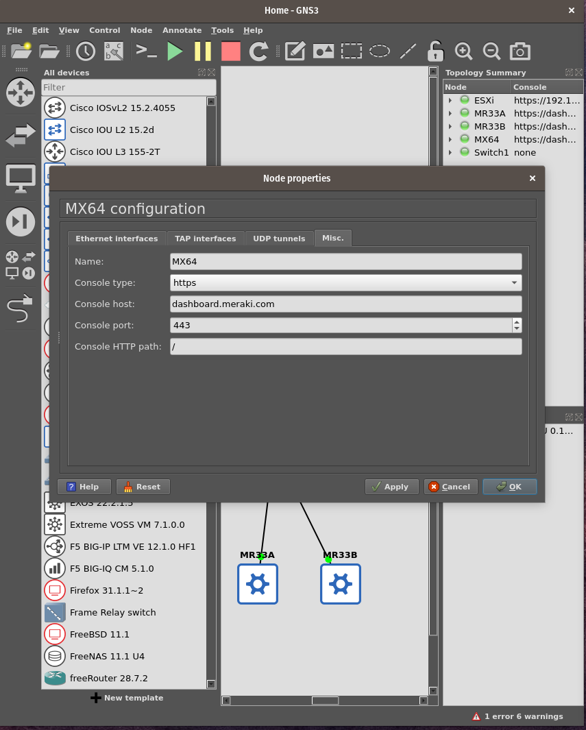
GNS3 allows double-clicking a device to open it’s terminal. To accomplish this with an outside device, right click the symbol and choose properties. Under properties, go to the “Misc.” tab. Here you set the link and point to an outside hyperlink. Since the Meraki is controlled from a centralized webpage, I selected console type “HTTPS” and used the URL to the controller, “dashboard.meraki.com”. You can specify telnet, vnc, spice, http, or https links in this way. The port defaults to 23 regardless of the protocol chosen, so you’ll need to update this. For https I selected 443.
Close the properties and try double-clicking! This cloud device functions as a “link” to an external URL. It doesn’t consume compute resources or memory, it’s just a way to hyperlink to an external resource. Note that all the devices in this example are managed from web pages, which I suspect will be a common case.
![]()
With the device in place, the GNS3 “Add a Link” tool can be used to draw connections. Here we run into a slight problem - clouds only have one interface by default (eth0). That means that GNS3 will only let you attach one link.
If you need extra links, go into the properties again and on one of the interface tabs add additional interfaces. You can easily add the loopback (lo0), or if you need a bunch just go to UDP tunnels and start adding tunnels.
In my case, all the Meraki appliances are managed from the Dashboard so I used a GNS3 switch to connect all the devices and changed it’s symbol to use the affinity blue icon. This doesn’t allow me to set a link on the switch symbol, but it was easy and also doesn’t tie up resources.
It’s important to keep in mind that using GNS3 network connections is being done for illustration, but they’re not going to “function” as GNS3 links. You can’t introduce error or capture packets, outside connects are just a graphical representation.
Just for fun, I wanted to have a red line connect over to ESXi because that is a trunk link. There’s not a way to color GNS3 links, so I used the line tool on the top icon bar. While this adds some pizzazz to the diagram, the resultant link isn’t attached and doesn’t move when the diagram is rearranged.
Using this Hyperlink technique can be a great help when documenting topologies or linking to outside dependent resources. Coupled with the ability to import images, it’s possible to make very functional and visually attractive topologies. It’s even possible to use this as a Visio replacement in simple cases, although you’re much more limited when doing diagrams in GNS3.